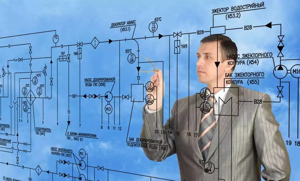
A Comprehensive Guide to P&ID Symbols in Automation Design
Piping and Instrumentation Diagrams P&IDs are essential tools used in the design and operation of industrial processes, particularly in automation systems. These diagrams represent the schematic flow of materials and the instrumentation involved in the process. P&ID symbols are crucial for engineers, designers, and operators to understand the system layout, as well as the components’ roles within that layout. This guide offers an in-depth exploration of P&ID symbols, focusing on their significance in automation design. Automation design heavily relies on the accurate depiction of instruments, control systems, and process components. A P&ID diagram, often created during the early stages of plant or system design, provides a visual representation of how all elements of a process are interlinked. The diagram includes various symbols that represent valves, pumps, sensors, instruments, and pipelines, along with the relationships between them. Understanding these symbols is fundamental for anyone working in process control, automation, and related fields. P&ID symbols are standardized to ensure consistency and prevent errors during system design and installation.

The symbols themselves are categorized based on the type of equipment or system they represent. For example, in automation design, symbols for instruments are key to illustrating the control systems that will regulate the process. These symbols may represent field instruments such as pressure transmitters, temperature controllers, and flow meters, each of which plays a critical role in maintaining system stability and performance. Automation relies on real-time data from these instruments to adjust the process as needed, making clear and accurate representation of these instruments in P&IDs vital. In automation design, P&ID symbols for control loops are also crucial. A control loop refers to the process where a control system automatically adjusts variables e.g., temperature, pressure to maintain a set point. These loops are represented using specific symbols for controllers, sensors, and final control elements such as valves or dampers. The symbols for these components, including the connections between them, enable engineers to visualize the closed-loop control process and ensure that the system will operate as intended.
Another important aspect of p&id symbols in automation is the depiction of safety and shutdown systems. Safety interlocks, emergency shutdowns, and alarms are integral parts of modern automation systems, and the proper use of symbols for these systems in P&IDs helps ensure that safety protocols are correctly integrated into the design. Symbols for emergency shutdown valves, bypasses, and safety instrumentation allow designers to communicate the design intent and provide operators with a clear understanding of how the system responds to abnormal conditions. The role of P&ID symbols extends beyond the design and construction phases of an automation system. These diagrams are invaluable during troubleshooting, maintenance, and operational phases. When an issue arises in an automated process, the P&ID serves as a roadmap, helping technicians identify which components are involved and which control systems need adjustment. By referencing the P&ID symbols, maintenance teams can quickly isolate faults and restore operations, reducing downtime and minimizing the impact of system failures.